
Go to the Start menu and select Programs, ASCOM Platform 6, ASCOM Device Hub.
Full information on operating the Device Hub is available under the Help menu. You will need to configure your telescope and Dome:
Click Tools / Setup
Under Telescope Setup click Choose, and use the ASCOM Chooser to select your telescope driver. Set up as required. Click OK.
Please see Synchronization Setup for the needed dome and telescope parameters. These numbers are used to calculate where on the dome surface the telescope is pointing, so it can line up the shutter with the telescope.
To set up MaxDome II, click Choose:
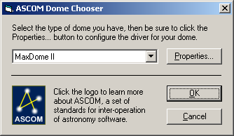
Select MaxDome II to choose the MaxDome II controller.
Click Properties... to display the Setup MaxDome II dialog box.

Select the COM Port that the MaxDome II controller is plugged into.
Tics Per Revolution must be set accurately in order to have correct dome positioning. Each tic is one half rotation of the motor drive shaft. If the shaft goes through 275 half-turns in a full dome rotation, enter 275. A typical value for a Sirius 2.3m dome is 227 (the actual value may vary slightly depending on installation).
Instead of counting tics manually, it is much simpler to click the Auto Calibrate button. The dome will start rotating to the right as seen from inside the dome. Note: if it goes left, the motor is wired backwards; stop and reverse the motor wires before proceeding. The dome will stop when it gets to the Home sensor, move a small distance forward, and then rotate fully around until it hits the Home sensor again. Once this is done, it will enter the measured Tics Per Revolution.
The location of the dome Home Position sensor determines the value for Home (deg). Enter the azimuth of the slit when the dome is in the home position. This is necessary for MaxDome to know where it is pointed. If you do not know the azimuth, use this procedure:
Click OK to go back to the ASCOM Dome Control Panel, and click OK to go back to the main controls.
Click Connect. Click Home to send the dome to the home position.
Guess at an approximate home position. North is 0 degrees, East is 90 degrees, South is 180 degrees, and West is 270 degrees. Open the Setup Dome dialog box and enter your guess.
Return to the main control panel. Rotate the dome a little to the left (manually or use the GOTO button), and then click the Home button.
After the dome stops, click the GOTO button and command it to point due North (0 degrees)
Check how well the dome lines up with the polar axis of the telescope mount. If it is not accurately aligned, estimate how much to adjust the Home position by and go back to Step 3. Repeat until the alignment is satisfactory.
If you wish to park the dome when you are not using it at a particular azimuth, enter an azimuth in Park (deg).
If your MaxDome II system includes a Shutter Controller card, turn on Has Shutter Control. If not, then turn it off. This affects what the MaxDome II driver reports to the controlling software.
If you wish to open only the upper shutter, turn on the Open Upper Only check box.
For some domes, there is a risk of an interference between part of the shutter mechanism and the telescope, when the dome and telescope are in particular positions. To avoid a collision, click Park Dome Before Operating Shutter. Set the Park position in a safe location where the shutter mechanism cannot touch the telescope. Now whenever the dome is commanded to close, the dome will first park. Note that the shutter will not move during the shutter operation, but it will move if a rotation command is received while it is fully open or fully closed. Also note that this setting is transferred to the MaxDome II Rotation Controller when the link is connected; a complete power failure for the controller could temporarily clear the setting until the link is reconnected.
If there is no risk of a shutter collision at any position, click Operate Shutter At Any Azimuth.
If the shutter is only partially opened, this can be reported as an error, or as "open". In some cases, e.g. manually adjusting the shutter to be partially opened, reporting an error could disable automation software. You can override this by setting Report Partially Open As to Open Shutter. Normally this should be left set to Error.
Click OK when you are done. The dome is now ready for use. The next step is to configure the dome slaving. This can be done using ASCOM or AutomaDome.
Advanced Settings
The optical sensor measures the dome azimuth. The optical sensor state is read every 10 milliseconds, and a decision is made as to whether the sensor is seeing "black" or "white". A tick is detected when a transition is seen from white to black or black to white. In order to ensure that clean transitions are seen, a "debounce" function is used. Debounce looks for a consistent reading for a period of time after a transition. By default, the debounce time is 120 ms, or 12 samples. This is suitable for domes where ticks occur approximately once a second, such as for Sirius Observatories dome installations.
Depending on the speed of the dome and the method of installing the optical sensor, the tick rate may be higher or lower. If it is higher you may need to reduce the Rotation Sensor Debounce time. It is recommended to set this to 1/8th of the normal tick interval during slewing. To set the debounce time, first make sure your control application is not connected. Select the debounce time from the drop list, and click Upload. You will be notified whether the upload was successful or not. The setting will be remembered by the rotation controller even if it is powered off. Please note that the drop list does not show the current setting for the board.
MaxDome Charger
If you are using the optional MaxDome Charger to maintain the shutter battery, turn on Enable Parked Charging. The charging system will engage whenever:
When the charger turns on, the communications link to the shutter will be disabled. The shutter will display Error status.
Some automation software may not like the (temporary) error condition. In this case it is possible to override the error display by turning on Hide Shutter Error.
The charging system will turn off automatically whenever a command is sent to slew or sync the dome, or if any shutter operation is commanded.