The first quirk in DSLRs is the reciprocal relationship between aperture and shutter speed. Photographers sometimes want to increase the depth of field by decreasing their aperture (f/stop), and increasing the exposure time to compensate. This allows objects at different distances to be in focus simultaneously. Alternatively, at a sporting event the photographer may wish to increase the aperture and decrease the exposure time to minimize motion blur.
SLR cameras were designed with convenient "stops", so that by moving one stop up in aperture and one stop down in exposure time gives the same density on the negative. For convenience, and because photographers are used to the concept, DSLR cameras are built the same way.
The practical result is that a DSLR camera on its own cannot produce an exposure of any arbitrary length.
Above 30 seconds most cameras need to be switched into "bulb mode". Most modern cameras can be switched and controlled automatically under computer control. Many older models require a "bulb cable".
A couple of models unfortunately cannot be automatically switched into bulb mode. In particular, Canon models whose shutter control dials have both an M and B setting have to be manually switched. This means you have to manually turn the dial depending on how long an exposure you plan to take. Unfortunately there is nothing that can be done about this in software as this is the way the manufacturer designed the camera. The two affected models are:
Canon 5D (original, not Mark II or higher): When using the camera with a bulb cable, always set Bulb Exposure to 1 and over, set the camera to Bulb mode, and always use exposures of 1 second or longer. If you need to take exposures shorter than 1 second, you will have to manually switch the camera to Manual mode (and then remember to switch it back to Bulb for longer exposures).
Canon 60D: When the dial is set to Manual mode, you can take exposures from 30 seconds down to 1/8000th of a second. When the dial is set to Bulb mode, you can any exposure duration you like; however, exposures shorter than approximately 0.05 seconds will not have very accurate exposure timing.
Bulb Cables
Older DSLR cameras cannot take exposures over 30 seconds without a special "bulb cable". This is in addition to the USB or Firewire connection, which is required for control and data transfer.
Bulb cables provided by the camera manufacturer are meant for standalone operation, so they have to be modified to work with a computer. Several astronomy vendors make aftermarket bulb cable adapters for use with computers. We recommend using a bulb cable that connects via USB. Serial port cables also work well, although most modern computers lack serial ports so a USB-to-Serial adapter is required; please be sure to use a high quality adapter to ensure proper operation. Some suppliers of bulb cables include Hap's Astro Cables, Oceanside Photo and Telescope, and Shoestring Astronomy. A handy DSLR Cable Tester is available on our web site. If you encounter problems operating your bulb cable, please check it first with this handy utility.
Some DSLR models that have the capability of taking long exposures without a bulb cable still require the cable if you want to use the mirror lockup feature. This feature can be very important because vibrations from the shutter and flip mirror can degrade long exposures. Please see the Camera and Autoguider Setup section for more information on your particular model.
DIY Bulb Cables
If you wish to assemble you own serial port bulb cable you will need to obtain the parts (all available at Tandy/Radio Shack) and have basic soldering skills. This section covers the serial cable portion for the Canon Rebel series.
The following parts are required:
|
Qty |
Part |
|
1 |
Resistor 47k |
|
1 |
Transistor 2N3904 |
|
1 |
Diode 1N4005 |
|
1 |
2.5 mm stereo audio plug |
|
1 |
Two conductor wire |
|
1 |
DB9 female connector |
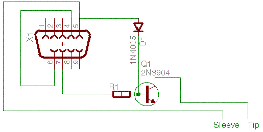
The circuit schematic diagram is shown below.
Other Canon EOS models (20D, 30D, 40D, etc) have the proprietary N3 connector. To accommodate these cameras, you can modify a standard Canon remote bulb cable, by breaking the cable and introducing a connector pair into the middle.
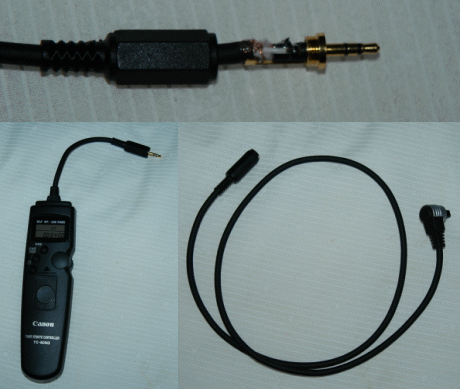
Connector details (top), and the two halves of the modified Bulb cable (bottom).
The bulb cable's connections are as follows:
|
Connector |
Wire |
Function |
|
Tip |
Red |
Shutter |
|
Center Ring |
White |
Focus |
|
Outer Ring |
Black |
Ground |
To prepare the modified Canon remote bulb cable:
Cut the bulb cable in two at a convenient point somewhere in the middle.
Strip all the wires. Trim to fit and tin each tip.
Unscrew the outer plastic cover on each connector.
The Male connector will go to the controller or the switch side.
The female end will go to the N3 plug side (camera side).
Make sure you thread the cable through the appropriate covers before soldering or you will have to do it all over again!
Solder the red wire to the tip lead, the white wire to the middle lead and the black wire to ground. Make sure that none of the leads or bare wires can touch. Use a small piece of electrical insulation tape to ensure this.
Ensure that the whole joint, cables ends and insulation all fit under the cover. The ground wire should take the tension for the cable so the white and red wires should not have loads on them if the cable is pulled.
Test the cable by checking the focus, then the shutter.
Now test the cable with the computer control.